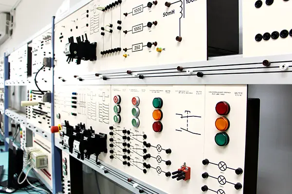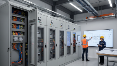

Pcc Panel Working matters because global buyers are purchasing operational reliability, not only a metal enclosure. A Power Control Center panel distributes and controls electrical power across factories, warehouses, hospitals, and infrastructure projects. Its performance affects motor starting, fault isolation, maintenance time, and production continuity. Small weaknesses can become expensive downtime.
The International Energy Agency’s Electricity 2024 report projects global electricity demand to grow by an average of 3.4% annually from 2024 to 2026. This pressure makes dependable distribution equipment increasingly important. Buyers must examine rated current, short-circuit withstand capacity, busbar design, protection coordination, and thermal performance. IEC 61439-2 provides a recognized framework for low-voltage power switchgear and controlgear assemblies. Compliance supports confidence, but it does not replace project-specific verification.
Look inside the panel.
A credible supplier should explain how breakers, contactors, relays, meters, and cables work together under normal and fault conditions. Factory acceptance testing, insulation checks, wiring inspections, and documented test results can reveal problems before shipment. Practical details matter, including clear labels, accessible terminals, adequate ventilation, and safe maintenance space. International buyers also need drawings, certificates, spare-parts guidance, and technical support across different time zones.
Still, a catalogue rating is not proof of field performance. Ambient temperature, dust, humidity, installation quality, and operator training can change results. This is where many purchasing decisions become too optimistic. Reviewing the manufacturer’s experience, third-party test evidence, and after-sales response creates a more reliable basis for comparing Pcc Panel Working across suppliers and markets.
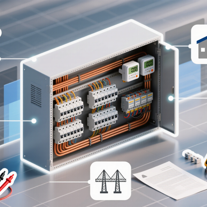
PCC panel working refers to how a Power Control Center panel receives, protects, and distributes electrical power. Incoming power usually arrives from a transformer, generator, or utility supply. The panel then sends electricity to separate feeders, motors, lighting systems, and production equipment.
Circuit breakers interrupt abnormal current, while meters show voltage, current, power factor, and energy use. In practical installations, operators may inspect these readings beside the panel during routine maintenance.
PCC panels are used in factories, warehouses, commercial buildings, water facilities, and infrastructure projects. Their internal layout often includes copper or aluminum busbars, protective devices, cable compartments, and control wiring. Proper separation helps reduce maintenance risks and limits faults.
However, a neat drawing does not guarantee reliable operation. Heat, dust, loose terminals, and incorrect cable sizing can still create problems. I have seen projects where documentation looked complete, but field conditions required changes.
Tips: Confirm the rated voltage, short-circuit capacity, enclosure protection, and feeder arrangement before purchase. Ask for wiring diagrams, routine test records, and material details. Check whether the design follows the required local or international standard. Do not assume one configuration suits every country. Installation conditions matter. Temperature, humidity, cable entry, maintenance access, and future load growth should all be reviewed with a qualified electrical engineer.
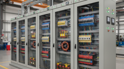
A Power Control Center (PCC) panel manages incoming electricity and distributes it to industrial loads. It also helps operators monitor voltage, current, and equipment status.
In daily operation, the process begins with a visual inspection. Technicians check cable connections, labels, ventilation, and grounding.
That check matters.
When the incoming supply reaches the panel, the main circuit breaker controls the connection. Measuring devices record electrical values and send signals to meters or a monitoring system.
Protection relays compare these values with configured limits. If current rises sharply, the relay can command the breaker to open.
This action isolates the affected circuit and limits equipment damage.
After the main busbar becomes energized, outgoing breakers feed motors, pumps, lighting, or other loads. Interlocks prevent unsafe switching sequences, while status indicators show whether each feeder is open, closed, or tripped.
An operator may start a feeder locally or through a control system, depending on the panel design.
During maintenance, the supply must be isolated, locked, and tested for absence of voltage.
In practical projects, correct settings are as important as strong hardware. Protection values should match the real load, cable capacity, and fault level.
A setting copied from another site may be wrong.
Commissioning teams usually perform insulation, continuity, relay, and functional tests before energizing the panel.
Still, field conditions can expose weaknesses that drawings miss, so records and periodic inspections deserve careful attention.
A Power Control Center (PCC) panel coordinates incoming power and distributes it safely to industrial loads. Its main components include a steel enclosure, copper or aluminum busbars, an incoming circuit breaker, outgoing feeders, and protective relays. Metering devices measure voltage, current, power factor, and energy consumption. These details help global buyers verify performance, operating costs, and maintenance needs.
The enclosure protects internal parts from dust, moisture, and accidental contact. Its IP rating should match the installation environment. Busbars carry high current, while insulation barriers reduce short-circuit risks. Circuit breakers interrupt abnormal current quickly. Current transformers support measurement and protection. Terminal blocks, control wiring, grounding bars, cooling systems, and cable glands complete the assembly. IEC 61439-2 requires verified design and performance for low-voltage switchgear assemblies. That requirement matters across different project locations.
A PCC panel can look impressive and still contain weak wiring practices. Inspection records matter. IEA’s Electricity 2024 report projects global electricity demand growth of about 4% annually through 2026. Rising demand increases pressure on reliable distribution equipment. Buyers should check temperature-rise tests, short-circuit ratings, component compatibility, and documentation before approval. Manufacturing quality is not always consistent. A small labeling error can delay commissioning. Clear drawings, routine testing, and traceable materials make the panel easier to install and service.
| Data Dimension | PCC Panel Component | Typical Technical Data | Primary Working Function | Why It Matters to Global Buyers | Recommended Inspection Focus |
|---|---|---|---|---|---|
| Power entry | Incoming circuit breaker | MCCB or ACB; commonly 400–4,000 A; interrupting capacity selected according to the prospective short-circuit current | Connects and isolates the main supply while providing overload and short-circuit protection | The correct rating protects equipment, supports safe maintenance, and helps match local fault-level requirements | Verify rated current, breaking capacity, trip settings, terminal arrangement, and coordination study |
| Current distribution | Main busbar system | Copper or aluminium conductors; current rating commonly 400–4,000 A; insulation and clearances designed for the assembly voltage | Distributes power from the incomer to outgoing feeders | Busbar sizing affects heat rise, voltage drop, service continuity, and the panel’s overall safety margin | Check material, cross-sectional area, joint torque, plating, phase spacing, supports, and temperature-rise design |
| Load connection | Outgoing feeder breakers | MCCBs, MCBs, or motor-protection devices sized for individual loads; feeder ratings vary with the connected load | Supplies and protects motors, distribution boards, heating systems, pumps, and other downstream loads | A well-configured feeder section improves selectivity and limits the impact of a downstream fault | Compare breaker ratings with load calculations, cable ampacity, motor starting current, and available spare ways |
| Motor control | Contactors, overload relays, and motor starters | Direct-on-line, star-delta, soft-starter, or variable-speed-drive arrangements according to motor size and process requirements | Starts, stops, reverses, and protects motors against overload or phase-related faults | Correct motor control reduces downtime, starting disturbances, and premature motor failure | Check motor current settings, duty category, interlocks, control sequence, thermal protection, and ventilation |
| Measurement | Meters and current transformers | Ammeter, voltmeter, multifunction power meter, and CTs selected for the system current and measurement accuracy | Monitors voltage, current, frequency, power, power factor, and energy consumption | Reliable measurements support energy management, preventive maintenance, and remote operating decisions | Verify CT ratio, accuracy class, polarity, meter configuration, communication interface, and calibration records |
| Protection and control | Protection relays and control relays | Overcurrent, earth-fault, under-voltage, phase-loss, or other functions selected through the protection design | Detects abnormal conditions and initiates tripping, alarms, or automatic control actions | Protection settings must work with the electrical network, utility requirements, and local safety rules | Review setting files, trip logic, relay wiring, discrimination, alarm contacts, and functional test results |
| Power quality and surge protection | Surge protection device | Type and voltage rating selected for the installation’s supply system and lightning or switching exposure | Limits transient overvoltage caused by lightning or switching events | Helps reduce damage to breakers, meters, drives, control equipment, and connected loads | Confirm system compatibility, backup protection, conductor length, earthing path, status indication, and replacement access |
| Control power | Control transformer or auxiliary power supply | Common control voltages include 24 V DC, 110 V AC, or 230 V AC, subject to the approved control design | Provides power for relays, indication lamps, PLC equipment, meters, and control circuits | A stable and appropriate control voltage improves operational safety and compatibility with site automation systems | Check primary and secondary ratings, VA capacity, fusing, isolation, polarity, and control-circuit labeling |
| Automation interface | PLC, remote I/O, or communication gateway | Optional equipment supporting status, alarms, remote control, and standard industrial communication networks | Exchanges operating data between the PCC panel and a supervisory or plant-control system | Supports remote monitoring, faster fault response, and integration with different project control architectures | Verify I/O list, communication protocol, address map, cybersecurity requirements, and point-to-point testing |
| Enclosure and environment | Metal enclosure, doors, gland plates, and ventilation | Indoor or outdoor construction; protection level selected for dust, water, access, corrosion, and installation conditions | Protects live parts and internal devices while providing mechanical strength and heat dissipation | Environmental suitability affects service life, personnel safety, shipping durability, and maintenance requirements | Confirm enclosure dimensions, ingress protection, material thickness, coating system, door seals, lifting points, and heat calculation |
| Safety and maintenance | Earthing system, neutral bar, barriers, and interlocks | Dedicated protective conductor connections, separated neutral arrangement where required, insulated barriers, and mechanical or electrical interlocking | Provides fault-current paths, prevents unsafe access, and supports safe isolation and maintenance | Clear safety provisions help satisfy site regulations and reduce risks during installation and operation | Inspect earth continuity, bonding points, warning labels, shrouds, door interlocks, segregation, and access clearances |
| Verification and compliance | Assembly design and routine verification | Design commonly assessed against IEC 61439 requirements, with routine checks for wiring, insulation, protective circuits, and operation | Confirms that the completed low-voltage switchgear assembly is built and tested according to the approved design | Documented verification simplifies project approval, import procedures, commissioning, and long-term maintenance | Request single-line diagrams, wiring diagrams, bills of materials, test reports, protection settings, manuals, and as-built documents |
Why Is PCC Panel Working Important for Global Buyers?
PCC panel working matters because it controls how electrical power reaches motors, machines, and production lines. A well-designed panel helps distribute current safely and reduces unexpected shutdowns. During factory inspections, buyers often look beyond the cabinet’s appearance. They check cable labels, busbar clearance, grounding points, and the quality of internal connections. Small details matter when equipment operates continuously in hot, dusty, or humid environments.
For global buyers, reliable PCC panel working also supports easier installation and maintenance. Clear wiring diagrams can save hours when technicians troubleshoot a fault. Proper protection settings help limit damage during overloads or short circuits. Buyers should request routine test reports, material specifications, and inspection records before shipment. These documents make technical claims easier to verify. They also support compliance with destination-market requirements, which can differ significantly.
Real projects are rarely perfect. A panel may pass testing but still need better access for future maintenance. I have seen projects where a cramped cable entry created avoidable delays. That weakness should not be hidden. Buyers can reduce risk by reviewing heat calculations, enclosure ratings, spare capacity, and emergency isolation arrangements. They should also confirm voltage, frequency, fault level, and communication needs in writing. A practical factory acceptance test, with simulated operating conditions, often reveals issues that drawings miss. Good performance depends on both engineering quality and careful coordination.
A PCC panel is important because it receives incoming power, distributes it to downstream loads, and supports protection and monitoring. The chart shows normalized three-phase AC voltage behavior at the two globally common power frequencies: 50 Hz and 60 Hz. Frequency compatibility helps buyers evaluate whether a panel is suitable for the target electrical system.
For global buyers, evaluating PCC panel performance starts with evidence, not polished photographs. Ask for single-line diagrams, rated current, short-circuit withstand data, and applicable IEC 61439 verification records. Confirm that the enclosure, busbars, breakers, and cable terminals match the approved design. A mismatch can create heat, vibration, or unsafe maintenance conditions. Check the stated IP rating against dust, moisture, and outdoor exposure.
During factory acceptance testing, inspect wiring labels, protective earthing, door alignment, and busbar clearances. Request insulation-resistance and dielectric-strength results from calibrated instruments. A functional test should confirm meter readings, interlocks, alarms, and breaker operation under simulated fault conditions. Ask how installers torque terminals and record each value. Loose connections may leave darkened insulation before failure becomes visible. Small details matter.
Performance also depends on thermal design. Review temperature-rise calculations and ventilation paths, then compare them with the panel’s actual load profile. An independent inspector can witness routine tests and verify serial-number traceability. Yet no checklist is perfect. Site conditions may differ from factory assumptions, and documentation can be incomplete. Buyers should allow time for corrective actions instead of accepting every report without questions. Test results are useful only when trained people connect them to real operating conditions.